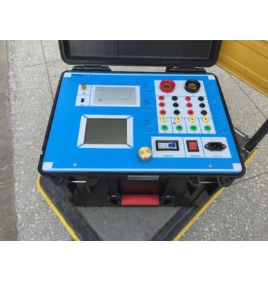

Partial discharge is a common phenomenon in high-voltage electrical equipment, which may lead to a decline in insulation performance and even cause serious faults. As an effective detection tool, the single-channel partial discharge tester can help technicians discover these problems in time, thereby taking preventive measures to ensure the safe and stable operation of the equipment. This article will discuss the working principle, characteristics, application scenarios, and usage methods of the single-channel partial discharge tester.
Working Principle
The working principle of the single-channel partial discharge tester is based on detecting electromagnetic signals generated during partial discharge. When partial discharge occurs inside high-voltage electrical equipment, it is accompanied by physical phenomena such as electromagnetic waves, sound, and light. The single-channel partial discharge tester captures these signals through built-in sensors and converts them into electrical signals, which are then processed by analysis software to determine the type, intensity, and location of the partial discharge.
Main Features
Anti-interference capability: Using digital filtering technology, it can effectively eliminate on-site interference and achieve partial discharge measurement even in strong interference environments.
High sensitivity: It can detect very small partial discharge signals, helping to identify potential problems early.
Portability: Small size and light weight make it easy to carry to the site for testing.
Intuitive operation interface: User-friendly interface design makes operation simpler.
Application Scenarios
The single-channel partial discharge tester is widely used in the following fields:
Power systems: Used to monitor the insulation status of high-voltage electrical equipment such as transformers, switchgear, and cables.
Manufacturing: Used for health monitoring of electrical equipment on production lines.
Research institutions: Used for scientific research and technological development.
Usage Methods
The following are the general steps for using the single-channel partial discharge tester:
Startup preparation: Adjust the time base mode to "ellipse" mode.
Calibration: Correctly connect the calibration pulse generator and start the calibration procedure.
After calibration: Disconnect the calibration connection line and remove the calibration pulse generator.
Connect to the test circuit: Connect to the high-voltage test circuit power supply, turn on the zero-mark switch, and slowly increase the test voltage until two zero-mark pulses appear on the display, with a phase difference of 180 degrees.
Adjust observation position: Rotate the "ellipse rotation" knob to a position convenient for observing the discharge, generally with the zero-mark pulses at the upper left and lower right of the ellipse.
Observe discharge: Continue to increase the voltage, pay attention to the continuous discharge that appears, and record the voltage when the discharge amount exceeds the specified low value, which is the partial discharge inception voltage.
Adjust display: At the set voltage, when observing the discharge pulse signal, adjust the amplifier switch so that the discharge pulse height is between 0.2 and 2 cm, then the discharge amount can be calculated from the reading on the digital meter.
Conclusion
The single-channel partial discharge tester, as an important preventive maintenance tool, plays an irreplaceable role in ensuring the safe and stable operation of high-voltage electrical equipment. With technological advancements, future single-channel partial discharge testers will become more intelligent and integrated, providing users with more efficient and accurate services.