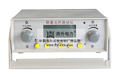

Partial discharge tester is a specialized instrument used to detect partial discharge phenomena in power equipment. This type of instrument is crucial for assessing the insulation condition of power equipment, predicting potential faults, and maintaining the safe operation of power systems. The following is a basic introduction to the partial discharge tester, including its working principle, usage steps, and applications.
Partial Discharge Tester: Working Principle and Applications
Introduction
Partial discharge tester is an important maintenance tool for power equipment, helping technicians to promptly identify insulation defects in power equipment and prevent equipment failures. This article will introduce the working principle, usage methods, and applications of the partial discharge tester in power equipment maintenance.
Working Principle
The working principle of the partial discharge tester is mainly based on the method of detecting high-frequency pulse currents. When partial discharge occurs in the insulation medium of power equipment under the action of an electric field, a brief high-frequency pulse current is generated in the circuit. These pulse current signals are captured through a coupling capacitor and transmitted to the input unit of the partial discharge tester. Subsequently, the signals undergo a series of processing steps, including low-noise pre-amplification, filtering amplification, and main amplification, ultimately presenting the characteristics of partial discharge on the display.
Usage Steps
Startup Preparation:
Ground the instrument properly.
Connect to AC power supply (usually 220V).
Set the display mode to "Ellipse" (default).
Discharge Quantity Calibration:
Connect the calibration pulse generator according to the wiring diagram.
Before applying the test voltage, use the calibration pulse generator for calibration.
Adjust the amplifier gain knob so that the injected pulse height is moderate (about 2cm) and matches the reading on the digital voltmeter.
Test Operation:
Turn on the power of the high-voltage test circuit.
Slowly increase the test voltage until two zero-mark pulses appear on the ellipse.
Continue to increase the voltage, paying attention to the first occurrence of continuous discharge; this voltage is the partial discharge inception voltage.
Adjust the amplifier gain knob to ensure that the PC reading on the digital meter does not exceed 100.0.
Use the "Ellipse Rotation" button to adjust the position of the ellipse so that the discharge signal is in the most favorable observation position.
Safety Precautions:
When replacing sensors, turn off the output voltage first.
Ensure all safety regulations are followed during the experiment.
Applications
Power Equipment Maintenance: Regularly test the insulation condition of transformers, cables, switchgear, and other power equipment.
Fault Diagnosis: When abnormalities occur in power equipment, use the partial discharge tester to locate the problem.
Quality Control: In the manufacturing process of power equipment, ensure that the electrical performance of products meets standards.
Conclusion
The partial discharge tester is an important tool for power system maintenance. By regularly using these instruments for testing, it is possible to effectively prevent power equipment failures and improve the reliability and safety of the power system.