
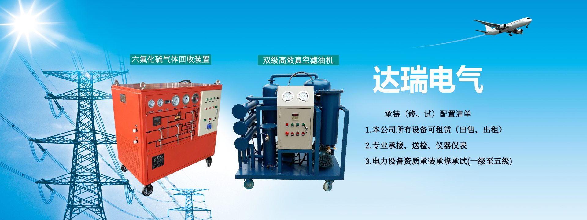
SF6 Gas Vacuum Pumping Device Introduction:
With the rapid development of the power industry, the investment in infrastructure and equipment, especially the continuous increase of SF6 electrical equipment, has led to higher requirements for installation, commissioning, maintenance, and repair of SF6 electrical equipment. Relevant departments have put forward higher quality and time requirements for vacuum pumping and refilling during the construction and maintenance of SF6 electrical equipment (especially GIS).
SF6 Gas Vacuum Pumping Device Structural Features:
It has comprehensive functions such as recovery, charging/discharging, purification, vacuum pumping, storage, and cylinder filling. The system is relatively complete; see Appendix I for the system diagram. The series or switching of each function is mainly accomplished by operating the electric control box and ball valves concentrated on one side of the panel.
The basic working principle of the recovery device is the freeze-liquefaction method. During recovery, the suction and compression properties of the compressor are used to draw SF6 gas at a certain pressure from SF6 electrical equipment into the compressor and compress it to a higher pressure. At the same time, utilizing the low evaporation temperature characteristics of R22 refrigerant, the higher-temperature SF6 gas is cooled to the condensation temperature for liquefaction and storage. This continuous suction continues until the SF6 compressor operates in series until the final recovery pressure is reached.
During charging/discharging, first use the vacuum pump of this device to evacuate the SF6 electrical equipment (or cylinders) and connecting pipelines, then directly use the pressure difference or the suction of the compressor to create a certain pressure difference to charge the SF6 from the storage container of the device into the SF6 electrical equipment until the required working pressure is reached. When cylinder filling is needed, the characteristics of the R22 refrigerant as mentioned above are simultaneously utilized to directly fill the liquefied SF6 into cylinders.
The purification function is completed simultaneously with the above recovery and charging/discharging functions.
The system is equipped with three oil separators, one installed at the outlet of the vacuum pump and two at the outlets of the compressor, to effectively remove oil carried by SF6 gas.
Insulating oil and gas construction equipment
1 Vacuum oil filter Unit 2 Oil purification capacity 6000L/h; Vacuum degree <60Pa
2 Dry air generator Unit 1 Dew point less than -40℃, reference flow 2m³/min
3 SF6 gas recovery device Unit 2 Pumping rate ≥40m³
4 SF6 gas vacuum charging device Unit 2 Pumping rate ≥45L/s
5 Vacuum pump Unit 2 ≥4000m³/h
Performance
Product model Vacuum pump rate (L/s) Ultimate vacuum
(pa) Vacuum pumping time (s)
170L340L680L1360L2700L5400L
SG208585≤5*10-22412204080
?Dimensions: 90cm×65cm×1200cm (length×width×height)
?Weight: about 350Kg
?Working voltage: 380~460V 50Hz AC
?Noise level: <78dB (A)