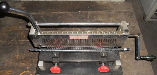

Provide hard punch gauge marking machine test range
1.This method specifies the self-calibration method for the hard punch gauge marking machine (referred to as marking machine) used for marking original gauge length in tensile testing of specimens.
2、Referenced standards GB/T228 "Metallic materials - Tensile testing at ambient temperature"
3、Calibration method for hard punch gauge marking machine: Use the marking machine to mark points on a specimen with a certain surface finish. Use qualified measuring instruments that have been verified to measure the distance between all points, record the measured values, and compare them with the calibrated gauge length to obtain the calibration result.
4、Calibration requirements
4.1 Calibration measuring tools The measuring tool used to measure the distance between marked points should be a qualified measuring tool verified by a legal verification department, and should be accurate to 0.02mm.
4.2 Calibration cycle The hard punch gauge marking machine should be calibrated once every six months.
4.3 Calibration personnel The calibration work is carried out by mechanical technical personnel. Hard punch gauge marking machine technical parameters: Model YD—300A YD—350A YD—400A YD—500A Gauge length range LO 5~300MM 10~350MM 10~400。。 10~500MM Division point spacing 5 or 10MM 10MM 10MM Applicable specimen specifications 1~400MM Gauge length accuracy ≤±0.5%(LO)
5、Calibration procedure: 5.1 The marking machine used for gauge marking should be sensitive, the spring of the hard punch gauge marking machine should be able to freely extend and retract, and the marked points should be as small as possible.
5.2 The specimen used for calibration should have a certain surface finish.
5.3 The points marked by the marking machine on the specimen should have a certain size specification. When the point diameter is greater than 1mm, the marking machine should be scrapped. The punch of the marking machine can be re-ground and reused, but it should be ensured that the center of the punch diameter is still at the center of the three adjacent points.
5.4 During calibration, the distance between two points should be measured from the center of one point to the center of another point. See the figure below (enlarged).
5.5 Randomly measure the distance between 20 adjacent points and record the data.
5.6 Randomly measure the distance between non-adjacent points. The requirements are as follows: Measure the distance between the first point and the point separated by 5 points. Then measure the distance between the second point and the point separated by 5 points. (The second point is separated from the first point by 2 points). Continue in this manner until all points are measured. Record each distance. Hard punch gauge marking machine measure the distance between the first point and the point separated by 10 points. Then measure the distance between the second point and the point separated by 10 points. (The second point is separated from the first point by 5 points). Continue in this manner until all points are measured. Record each distance. Measure the distance between the first point and the point separated by 15 points. Then measure the distance between the second point and the point separated by 15 points. (The second point is separated from the first point by 7 points). Continue in this manner until all points are measured. Record each distance. Measure the distance between the first point and the point separated by 20 points. Then measure the distance between the second point and the point separated by 20 points. (The second point is separated from the first point by 10 points). Continue in this manner until all points are measured. Record each distance.
5.7 The relative error between the data measured in any single measurement and the specified data should not exceed ±1.0%.