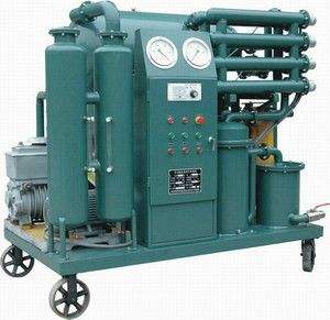
This machine consists of a gear pump 1, a filter 4, a safety valve 5, an oil return valve 3, a drain valve 7, a filter bed 8 (including pressure gauge, filter plates, filter frames, filter paper, oil pan), front support 12, rear support 9, chassis 11, tie rods 13, coupling 10, and an electric motor installed on the chassis and under the filter bed. The filter is installed on the front side of the gear pump, with an oil return valve mounted on it, connected to the oil pan via a PVC pipe. The filter bed is installed on the gear pump and on top of the front and rear supports, where filter plates and filter frames (see Table 1) are alternately arranged to form individual filtering chambers, with filter paper sandwiched between the plates and frames. The oil inlet and outlet hoses are connected to the inlet and outlet pipe joints 15 and 6. The oil to be filtered is drawn in through the oil inlet hole of the filter, passes through the filter to remove larger impurities, and then enters the gear pump. As the motor drives the gear pump to rotate through the coupling, the gears exert pressure on the oil, causing it to flow into the filter bed, permeate through the filter paper, and filter out impurities from the oil. Due to the capillary action of the filter paper, residual moisture in the oil is absorbed. The filtered oil is then discharged from the oil pipe. The safety valve controls the pressure in the piping system; when the oil pressure exceeds the specified value, the safety valve immediately activates, allowing the oil to circulate within the pump without further pressure increase, ensuring safe operation of the equipment. The oil return valve, utilizing the vacuum effect at the gear pump inlet, draws oil from the oil pan into the filter. The drain valve is provided for taking oil samples for withstand voltage and other physical and chemical performance tests. Since this machine adopts a chassis with rollers 14, it can be moved by pulling the tie rods manually.
IV. Supporting Products
Electric heating constant temperature oven, a supporting product for the plate-and-frame pressure oil filter, used for drying filter paper; it can also be used independently in factory, school, or hospital laboratories for baking and drying non-volatile, non-flammable items.
Hole puncher, a supporting product for the oil filter, used for punching inlet and outlet holes in filter paper.
V. Model Description

VI. Adjustment and Test Run
a) The placement of filter plates, frames, and paper on the filter bed should be as follows: place three sheets of filter paper close to the thrust plate and the tightening plate at each end, then place a filter plate, and then alternate filter plates and frames in sequence, with two sheets of filter paper sandwiched between each plate and frame. The filter plates and frames have triangular support lugs on one side and arc-shaped support lugs on the other, which rest on two support rods (plates). The triangular and arc lugs of the filter plates and frames must be on the same side as those on the tightening plate, and the triangular lugs must be installed on the oil inlet side; otherwise, the filtering capability will be lost. Both filter plates and frames should be positioned with the arc support lug side against the support rod. Filter paper should be clean and dry; if using cleaned and dried old filter paper, place the dirty side facing the filter frame to prevent impurities from being washed off and contaminating the filtered oil. After installing the filter plates and frames, recheck the positions, then rotate the handle to tighten. Do not extend the tightening handle, and only one person should operate. Finally, cover the oil pan. (Filter paper dimensions are shown in the attached drawing at the end.)
b) When connecting the power supply, the entire machine should be grounded. Check that all connections are tight. Rotate the machine by hand forward and backward for three or four turns to see if there is any jamming. If everything is normal, jog the motor to check that the pump rotation direction matches the arrow direction; it must not be reversed.
c) The oil filter's inlet and outlet are connected to the oil storage tank via hoses, and all control valves should be fully opened, with the oil return valve and drain valve closed. Only when everything is ready should the machine be started.
d) After running for one minute, if the pressure gauge pointer reads around 0.25 MPa, it is normal. If the pointer exceeds 0.5 MPa, stop the machine to check for faults, and restart after troubleshooting.
VII. Operating Procedures
a) Operators must be familiar with the machine's performance and debugging methods.
b) Clean the piping system and the machine's internal cavity.
c) After starting the machine, frequently check the pressure gauge readings and the machine's operation. If any abnormality occurs, stop the machine immediately, troubleshoot, and then restart.
d) Based on the oil filtration capacity, after circulating and filtering 2-3 times the oil volume, open the drain valve, take an oil sample for testing, and continue until it meets the requirements.
e) After a certain period of operation, if the pressure rises above 0.5 MPa or drops compared to the initial pressure, it indicates that the filter paper has been punctured or has absorbed a large amount of moisture, causing the capillary pores to expand; both conditions mean the filtering capability is lost.
f) The safety valve has been inspected and adjusted before leaving the factory and is sealed with a lead seal; do not disassemble it arbitrarily. If adjustment is truly necessary, it must be tested and qualified before continued use.
g) During operation, pay attention to the oil level. If there is excessive oil in the oil pan, open the oil return valve to drain the oil from the pan, then close the valve.
h) If the oil contains excessive moisture, heat the oil to evaporate some of the moisture, and filter after it cools to room temperature.
i) After filtration is complete, clean the machine, apply anti-rust oil, and store it in a dry, ventilated place.
VIII. Machine Maintenance and Care
a) All sealing surfaces should be coated with anti-rust oil when not in use to prevent corrosion (such as filter plates, frames, thrust plate, tightening plate, etc.).
b) Clean the filter screen, trapezoidal screw, etc., and apply anti-rust oil.
c) All pipe joints should be wrapped and sealed to prevent foreign matter from entering the piping system.
d) During movement, prevent impact and tipping to avoid damaging the machine and reducing its performance.
e) The product should not be stored outdoors to avoid wind, rain, sun, dew, and dust. If conditions are limited and outdoor storage is unavoidable, take rain protection measures.
IX. Usage Restrictions
This machine is prohibited from use under the following conditions:
a) Altitude exceeding 1000 meters.
b) Ambient temperature higher than +40°C or lower than -10°C.
c) Relative air humidity greater than 85%.
d) In places with explosion-proof requirements, an oil filter with an explosion-proof motor must be selected.
e) Environments without rain protection or filled with water vapor.
f) Filtering gasoline, kerosene, and volatile liquids containing acids or alkalis.