
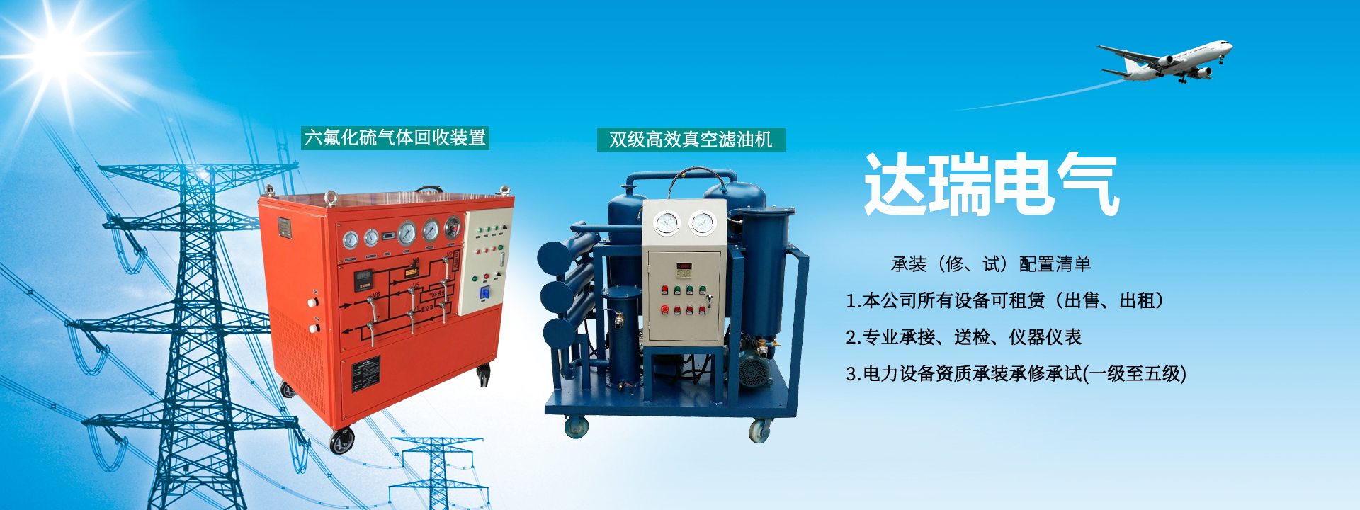
SF6 Gas Vacuumizing and Refilling Device
With the rapid development of the power industry, the construction of infrastructure and the investment in equipment, especially the continuous increase of SF6 electrical equipment, the requirements for installation, commissioning, maintenance, and overhaul of SF6 electrical equipment are getting higher and higher. Relevant departments have put forward higher quality and time requirements for vacuumizing and refilling during the construction and maintenance of SF6 electrical equipment (especially GIS). To meet the needs of this development, based on years of experience in testing, inspection, and professional technical accumulation of SF6 gas electrical equipment, and through analysis of the latest and most advanced maintenance equipment abroad, our company has developed the SF6 Gas Vacuumizing and Refilling Device, which not only meets the technical index requirements of advanced foreign equipment but also satisfies the price requirements of domestic users.
SF6 Gas Vacuumizing and Refilling Device is mainly used in power supply companies, power transmission and transformation engineering companies, power plants, ultra-high voltage transmission and substations, SF6 electrical switch manufacturing plants, and other departments, as auxiliary equipment for installation, commissioning, and maintenance of SF6 electrical products such as GCBP, GCBT, and GIS. This device is used to vacuumize and refill SF6 gas for the above electrical products, and it can also be used as equipment for vacuumizing and refilling gas in other departments.
Product Features
1. It has comprehensive functions such as recovery, charging/discharging, purification, vacuumizing, storage, and cylinder filling, with a relatively complete system. The series connection or switching of each function is mainly completed through the electric control box and ball valves concentrated on one side of the panel.
2. The basic working principle of the recovery device is to use the freezing and liquefaction method. During recovery, the suction and compression characteristics of the compressor are used to draw SF6 gas at a certain pressure from SF6 electrical equipment into the compressor and compress it to a higher pressure. At the same time, utilizing the low evaporation temperature characteristics of R22 refrigerant, the higher temperature SF6 gas is cooled to the condensation temperature for liquefaction and storage. This continuous suction is carried out until the SF6 compressor operates in series until the final recovery pressure is reached.
3. During charging/discharging, first use the vacuum pump of this device to vacuumize the SF6 electrical equipment (or cylinder) and connecting pipelines, then directly use the pressure difference or use the suction of the compressor to create a certain pressure difference to fill the SF6 from the storage container of the device into the SF6 electrical equipment until the required working pressure is reached. When cylinder filling is needed, the characteristics of the R22 refrigerant as mentioned above are also used to directly fill the liquefied SF6 into the cylinder.
4. The purification function is completed simultaneously with the above recovery and charging/discharging functions.
5. Three oil separators are installed in the system, one at the outlet of the vacuum pump and two at the outlet of the compressor, to effectively remove the oil carried by the SF6 gas.
6. A drying filter is installed in the system circuit to ensure the purity of the SF6 entering the storage container and effectively remove moisture. The filter is equipped with a heating regeneration device, which can be heated and regenerated under vacuum, allowing the molecular sieve to be reused.
7. The system is equipped with reliable safety protection devices. A high-pressure pressure controller is installed at the exhaust port of the SF6 compressor. Once the exhaust pressure exceeds the limit value, it will automatically stop the compressor, and restart after the pressure drops. A safety valve is installed on the storage container. Once overpressure occurs, the safety valve automatically opens to release gas, and automatically closes after the pressure drops.