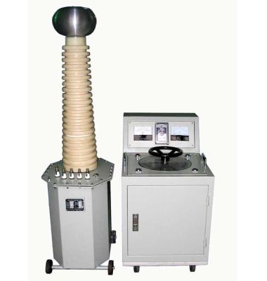

The following is an article about "Loop Resistance Tester: A Comprehensive Analysis from Principle to Practice", which details the working principle, main functional features, and operation methods in practical applications of the loop resistance tester:
Loop Resistance Tester: A Comprehensive Analysis from Principle to Practice
Introduction
In power systems, industrial equipment, and building electrical installations, the contact resistance of electrical connection points is an important safety indicator. As a professional detection tool, the loop resistance tester can accurately measure the resistance value of these connection points, ensuring the safety and reliability of the electrical system. This article will start from the working principle, introduce the functional characteristics of the loop resistance tester in detail, and provide practical operation guidelines.
Working Principle of Loop Resistance Tester
The loop resistance tester is mainly used to measure the contact resistance of electrical connection points. Its working principle mainly includes the following aspects:
DC Injection Method:
Current Injection: The tester injects a stable DC current into the loop under test.
Voltage Measurement: By measuring the voltage drop across the loop, according to Ohm's law
Test Current Range: Generally from a few amperes to several hundred amperes to ensure sufficient measurement sensitivity.
Four-Terminal Method (Kelvin Clamp Method):
Current Terminals: One pair of terminals is used to inject current.
Voltage Terminals: Another pair of terminals is used to measure the voltage drop, avoiding the influence of lead resistance on the measurement results.
Improved Accuracy: This method can provide more accurate measurement results, especially when measuring low resistance values.
Temperature Compensation:
Temperature Effect: Resistance values change with temperature.
Compensation Function: Advanced testers have temperature compensation function to ensure accurate measurement results under different temperature conditions.
Main Functions and Features
High-Precision Measurement: Can accurately measure tiny resistance values, with a measurement range typically up to micro-ohm (μΩ) level.
Multiple Measurement Modes: Supports different test currents and measurement modes to adapt to different application scenarios.
Data Recording and Analysis: Built-in memory can record a large amount of test data and supports data export and analysis.
User-Friendly Interface: Provides a graphical operation interface, making parameter setting and result reading simpler.
Safety Protection: Equipped with overload protection, reverse connection protection, and other safety measures to ensure the safety of operators and equipment.
Practical Applications and Operation Guide
Preparation:
Safety Check: Ensure that the device under test is powered off and has undergone appropriate safety checks.
Select Current: Choose the appropriate test current according to the test requirements.
Connect Equipment: Correctly connect the current terminals and voltage terminals of the tester to the loop under test.
Connecting the Tester:
Four-Terminal Connection: If using the four-terminal method, ensure that the current terminals and voltage terminals are connected to different positions respectively.
Wiring Confirmation: Check that all wiring is secure to avoid looseness.
Starting the Test:
Start the Tester: Start the device according to the tester's operation manual.
Read Results: Wait for stable current injection, read the voltage drop, and calculate the resistance value.
Record Data: Record the test results and save the data for subsequent analysis.
Precautions:
Safety First: Confirm that the loop under test is completely powered off before testing to avoid electric shock hazards.
Test Current Selection: Use the correct test current; too high or too low will affect the measurement results.
Regular Calibration: Regularly calibrate the tester to ensure its measurement accuracy.
Environmental Conditions: When used in high temperature or humid environments, pay attention to the equipment's heat dissipation and waterproofing.
Practical Cases
Substation Maintenance: During routine maintenance, a substation used a loop resistance tester to test multiple electrical connection points, promptly discovered several poor contact issues, and repaired them, ensuring the safe operation of the power grid.
Industrial Equipment Testing: During motor repair in a factory, a loop resistance tester was used to detect the contact resistance of motor windings, found a poorly contacted joint, and replaced it in time, avoiding equipment failure.
Future Trends
With the development of technology, future loop resistance testers will become more intelligent and portable. For example:
Internet of Things (IoT) Technology: Enables remote monitoring and data transmission.
Big Data Analysis: Optimizes detection processes.
Artificial Intelligence (AI): Performs fault prediction and health management.
Conclusion
With its high precision, multifunctionality, and user-friendly features, the loop resistance tester plays an important role in the maintenance and detection of electrical systems. By correctly using the loop resistance tester, the safety and reliability of electrical connections can be significantly improved, ensuring the normal operation of electrical systems. Whether in power systems or industrial equipment, the loop resistance tester is an indispensable important tool.
References
List the relevant literature, standards, and specifications referenced in this article to ensure the accuracy and reliability of the information.
Through this article, readers can comprehensively understand the working principle, functional characteristics, and application methods of the loop resistance tester in practical operations.