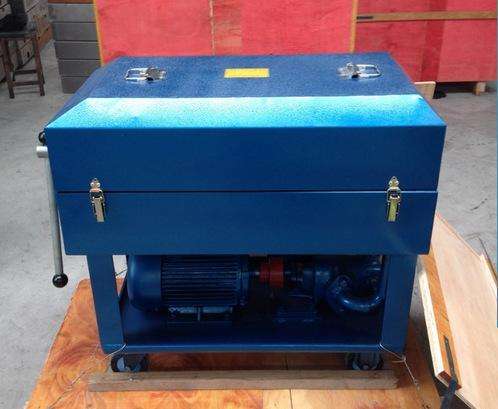
Plate and Frame Filter Press Filter Paper Plate Frame Structure
1. It has the advantages of simple structure, easy operation, low operating cost, and is not limited by site conditions.
2. It adopts a high-pressure, low-noise vane pump, which is small in size, light in weight, convenient to use, and stable in performance.
Optional overall structure:
1. Cast iron plate frames or engineering plastic plate frames can be selected.
2. High-temperature resistant water-cooling configuration is optional for filtering high-temperature hot oil.
Structural Features
1. The oil filter is a movable device composed of a filter bed, an oil pump, and a coarse filter.
2. The filter bed can operate continuously, pressing dirty oil into the side-filtering filter under pressure. The filter consists of a complete set of alternately arranged filter plates and filter frames, and a mechanism including a manual screw pressing device and a pressing plate. The sides of the filter plates and frames have "ears" supported on the support plate of the frame. Filter paper (or filter cloth) as the filtering medium is interposed between the plates and frames to perform filtration. Two liquid passage holes are provided at corresponding positions on the filter plates and frames, forming two complete channels when pressed together. The triangular side of the ears introduces dirty oil, which, after filtration in the filter chamber, is drawn out from the other corresponding channel (on the fan-shaped side of the ears) as clean oil.
4. During filtration, dirty oil is distributed into each filter frame through the input channel, and impurities are filtered out onto the filter plates through the filter paper, then collected in the output channel and discharged outside the machine. The dirt remains on the surface of the filter paper, and a small amount of moisture in the dirty oil is absorbed by the capillaries in the filter paper. When the filter residue on the surface of the filter paper gradually thickens and the moisture content in the filter paper increases, the filtration resistance increases. When it increases to a certain extent (generally 0.2-0.35 MPa), filtration should be stopped, and after replacing the filter paper, continue use.
5. The gear pump is connected to the motor with an elastic rubber pad. To avoid mechanical accidents caused by excessive pressure, a safety valve is provided at the lower part of the oil pump (it has been adjusted to the specified maximum pressure value before leaving the factory). According to user needs, the safety valve can be adjusted to a lower value, but it is not allowed to be adjusted to exceed the specified maximum pressure value.
6. The oil pump and motor are installed below the filtration part, and the liquid output by the oil pump is delivered to the filtration part through the discharge pipe and thrust plate.
7. The gear of the oil pump is supported by rolling bearings, and it is lubricated by the oil delivered by the pump itself. The fine filter is installed at the suction end of the oil pump to prevent large particles from entering the pump and damaging it. By removing the cover of the coarse filter, the filter screen can be directly taken out for cleaning, because if the coarse filter is full of dirt, it will not only rapidly reduce the filtration capacity but also possibly damage the filter screen.
8. When there is residual oil in the tank, the return oil valve can be opened to suck away the residual oil, preventing it from overflowing and leaking outside the machine.