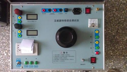

A simulated partial discharge tester is a specialized device used to detect partial discharge phenomena in power equipment. Such testers are typically used in laboratory environments to reproduce, in a simulated manner, the partial discharge conditions that may occur in power equipment during actual operation. The following is an outline of an article about the simulated partial discharge tester:
Working Principle and Application of Simulated Partial Discharge Tester
Partial discharge (PD) refers to the localized electrical breakdown phenomenon that occurs in the insulation material of power equipment. These discharges can be early signs of potential faults in the equipment and may lead to further deterioration of the insulation material, ultimately resulting in equipment failure. A simulated partial discharge tester is an instrument used to simulate partial discharge phenomena under controlled conditions, primarily applied in the research and development, quality control, and maintenance of power equipment.
Characteristics of Simulated Partial Discharge Tester
Multi-channel detection: It can simultaneously detect multiple signal sources, suitable for testing complex power systems.
Wide frequency band coverage: It typically has a broad frequency response range, capable of capturing different types of partial discharge signals.
Portable design: Some models of simulated partial discharge testers are designed to be portable, facilitating on-site use.
Combination of analog and digital: It combines the advantages of analog and digital technologies to improve testing accuracy and reliability.
Main Components and Functions
Coupling capacitor (Ck): Used to extract the pulse current signals generated by partial discharge from the equipment under test.
Preamplifier: Used to amplify and filter the signals from the coupling capacitor.
Filter amplifier: Selects the required frequency bandwidth to isolate interference signals.
Main amplifier: Further amplifies the signal to meet display requirements.
Display unit: Provides a visual interface to display partial discharge pulses.
Time window unit: Allows selection of time periods within each voltage cycle for pulse peak measurement, helping to exclude fixed-phase interference.
Test Steps
Preparation phase: Ensure the tester is calibrated and all connections are correct.
Set parameters: Set appropriate test parameters, such as frequency range and gain, based on the characteristics of the equipment under test.
Start testing: Apply the test voltage and observe partial discharge phenomena through the tester.
Data recording: Record characteristic parameters of partial discharge, such as discharge amplitude and repetition rate.
Data analysis: Analyze the recorded data to determine whether partial discharge exists and its severity.
Application Cases
Case 1: During routine maintenance of a power transformer, a simulated partial discharge tester detected abnormal partial discharge signals. Further diagnosis revealed that it was caused by aging of the winding insulation material, and the hidden danger was eliminated by replacing the damaged components.
Case 2: During type testing of high-voltage cable terminations, a simulated partial discharge tester detected unexpected partial discharge phenomena, indicating design issues with the cable termination. The problem was resolved by improving the design.
Conclusion
The simulated partial discharge tester plays an important role in the research and development, production, and maintenance of power equipment. By accurately simulating partial discharge phenomena, potential problems in equipment can be detected in advance, allowing necessary measures to be taken to prevent failures and ensure the safe and stable operation of the power system.
The above content provides a basic overview of the simulated partial discharge tester. It should be noted that actual operational steps and usage techniques may vary depending on the model of the tester. Before use, please carefully read the user manual provided by the manufacturer and ensure all safety guidelines are followed.