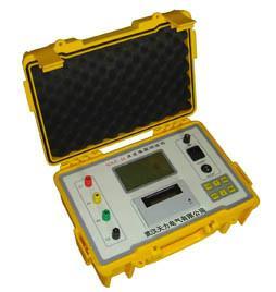

The resistance measured under DC conditions is called DC resistance. In power plants and power grids, it is often necessary to measure DC resistance. For example, the DC resistance of the motor armature winding, the DC resistance of the transformer winding, the DC resistance of the circuit breaker conductive loop, etc. Therefore, DC resistance measurement is one of the indispensable test items in electrical equipment handover, maintenance, and preventive tests.
In the use of the DC resistance tester, wiring is a crucial part. Users should pay attention to the wiring of the equipment. Today, the editor will introduce the wiring precautions of the DC resistance tester to everyone.
1. Use the power cord to connect the instrument to the external AC220 power supply, and use the grounding wire to connect the grounding terminal to the earth.
2. When testing a two-winding transformer, sequentially connect the four test clamps (yellow, green, red, black) of the high-voltage test lead (longer) to the A, B, C, O bushings on the high-voltage side. If there are only three bushings A, B, C, the black test clamp of the DC resistance tester can be left hanging; connect the other end of the test lead to the corresponding terminal of the instrument. Connect the three test clamps (yellow, green, red) of the low-voltage test lead (shorter) to the a, b, c bushings on the low-voltage side, and connect the other end of the test lead to the corresponding terminal of the instrument.
3. For a three-winding transformer, after testing the high and low voltage windings, you can reverse the four test clamps of the high-voltage test lead (longer) to the medium-voltage side for testing.
4. For a single-phase transformer, use the yellow and green test clamps of the high-voltage test lead (longer) to connect to the high-voltage side of the single-phase transformer, and the yellow and green test clamps of the low-voltage test lead (shorter) to connect to the low-voltage side of the single-phase transformer. Connect the other end of the test lead to the corresponding terminal of the instrument.
5. The special test lead provided with the instrument has the current and voltage lines designed on the same clamp, making wiring simple and convenient.
When the DC resistance tester is turned on without the circuit properly connected, the meter displays "E0000". After connecting the measurement leads, select the desired resistance range based on the measured value, press the switch for that range, and the indicator light will turn on. The stable value displayed on the four-and-a-half digit LCD is the measured resistance value. When reading the value, pay attention to the unit on the selected range. When measuring large inductive samples such as power transformers, it is recommended to short-circuit other coils not being measured in the test circuit to avoid electromagnetic interference.