
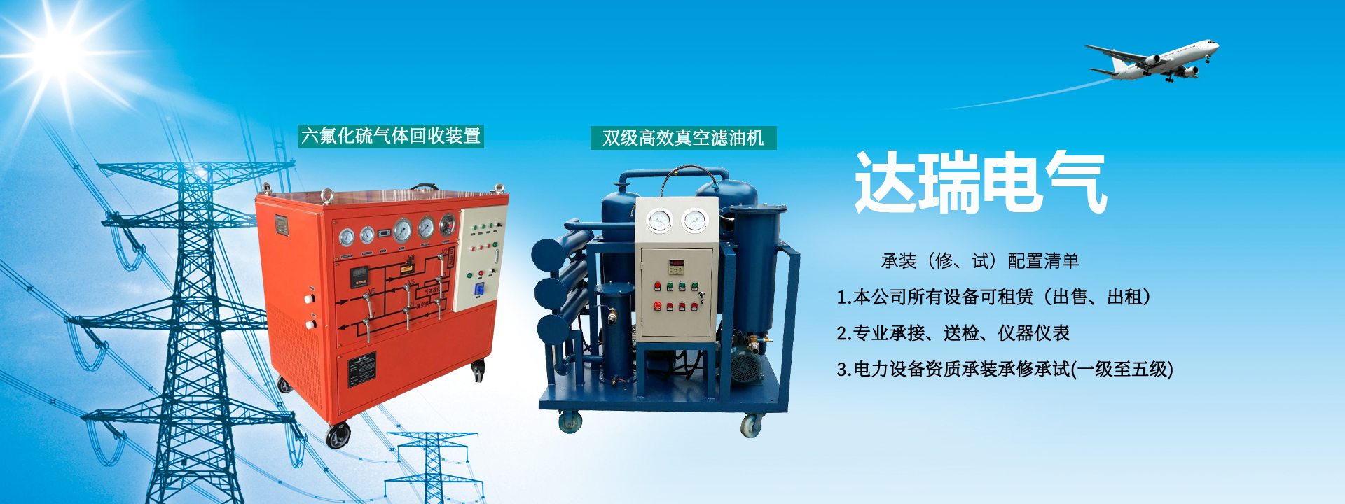
HDQH Sulfur Hexafluoride Gas Recovery and Filling Device Operation Instructions and Precautions
The operation to enter the working state should be carried out only after completing the relevant work in Section 4.
This device has five basic functions: vacuum pumping, recovery and storage, charging and discharging, cylinder filling, and purification and drying, as well as corresponding combined functions. The operations for each function are described below. Refer to the operation panel flowchart in Appendix 4. Pay attention to the sequence of operations.
All valves are assumed to be closed at startup.
1. Vacuum Pumping
This refers to pumping the device or system from atmospheric pressure to the ultimate vacuum or the specified vacuum level of the device.
Points to note:
a) Start the vacuum pump to evacuate. Decide whether to connect the exhaust pipe to the outdoors as needed.
b) When starting the vacuum pump, ensure that the pressure of the device or system being evacuated is at zero gauge pressure or below.
c) Whenever it is necessary to observe the vacuum level, open valve V8, and close valve V8 promptly after observation.
d) Do not start the SF6 compressor while maintaining vacuum.
When starting up or when the device is exposed to the atmosphere, the device itself should be evacuated first. See Table ① below for operation methods.
When recovery is needed, the connecting pipes should be evacuated first (the valve at the outlet of the electrical equipment connected to the hose should be closed at this time). See Table ② below for operation methods.
When cylinder filling is needed, the operation method is the same as above. See Table ③ below.
2. Recovery and Storage
This refers to recovering the SF6 gas from electrical equipment into the storage container of the device, generally from the initial recovery pressure to the final recovery pressure of the device or the specified final recovery pressure.
(1) After connecting the pipes, first determine whether it is necessary to evacuate the device or pipes. Refer to Section 1 of this section for judgment and operation methods regarding vacuum pumping.
(2) Start the refrigeration compressor half an hour to one hour in advance based on the ambient temperature during recovery and the amount of gas to be recovered, and keep it running until the recovery is complete.
(3) At the beginning of recovery, when the initial recovery pressure (M1) is high, open V7, half-open V2, V3, and the SF6 compressor.
(4) After startup, pay attention to the discharge pressure gauge (M2) of the SF6 compressor. The pressure reading on M2 should be less than 2.0 MPa. The compressor outlet is connected to a pressure controller. If the reading reaches the limit of 2.0 MPa, the pressure controller will automatically cut off the compressor operation. After the pressure drops and stabilizes, restart the compressor. Therefore, when the discharge pressure rises too quickly, the opening of the compressor inlet valve V2 can be appropriately adjusted to control it.
(5) During the recovery process, observe the liquid level in the storage container through the sight glass. The high liquid level should not exceed 2/3 of the sight glass.
(6) When the recovery reaches the final recovery pressure or the predetermined value, the recovery work is completed.
(7) Turn off the refrigeration compressor, close V3, the SF6 compressor, V2, and V7.
3. Charging and Discharging
This refers to charging the SF6 stored in the device's storage container into electrical equipment until the required working pressure is reached.
(1) After connecting the pipes, first determine whether it is necessary to evacuate the electrical equipment and pipes. Refer to Section 1 of this section for judgment and operation methods regarding vacuum pumping.
(2) When the storage container pressure is high, open V4 and directly charge the electrical equipment. Observe the M6 pressure gauge reading.
(3) When the storage container pressure drops and it is no longer possible to directly charge the electrical equipment, connect an external gas source at V7 and charge the electrical equipment directly through V7 and V6; or if the external gas source pressure is low, use the compressor to charge the SF6 from the external gas source into the electrical equipment. In this case, close V6, open V7, V2, V3, the SF6 compressor, and V4 until the required working pressure is reached.
(4) When stopping, the SF6 in the system should be recovered into the storage container using the compressor until the suction pressure (M1) reaches zero gauge pressure. Then turn off the SF6 compressor and related valves.
4. Cylinder Filling
Cylinder filling refers to directly recovering the SF6 from electrical equipment and filling it into steel cylinders.
(1) After connecting the pipes, first determine whether evacuation is needed. The recovery pipes and the pipes connected to the steel cylinder can be evacuated together.
(2) Start the refrigeration compressor in advance.
(3) Open V7, V2, the SF6 compressor, V3, V4, and the steel cylinder valve to perform cylinder filling.
(4) During the cylinder filling process, pay attention to the discharge pressure of the SF6 compressor. If it approaches 1.9 MPa, a switching operation should be performed to release the high-pressure gas at the top of the steel cylinder into a low-pressure container.
(5) Switching operation: Close V7 and V4, then quickly open V5 for about 1 to 2 minutes. The operator should judge the timing. When resuming liquid filling, close V5, open V7, and quickly open V4. This switching can be repeated until the steel cylinder is full.
(6) After the steel cylinder is full, close V7, V4, and the steel cylinder valve. Use the compressor to evacuate the liquid remaining in the pipes until the M1 pressure gauge reaches zero gauge pressure. Then turn off the SF6 compressor, cooler, refrigeration compressor, and related valves.
Note: Cylinder filling refers to the situation where there is already a certain amount of SF6 liquid in the storage tank, and the liquid level can be observed at any time.