
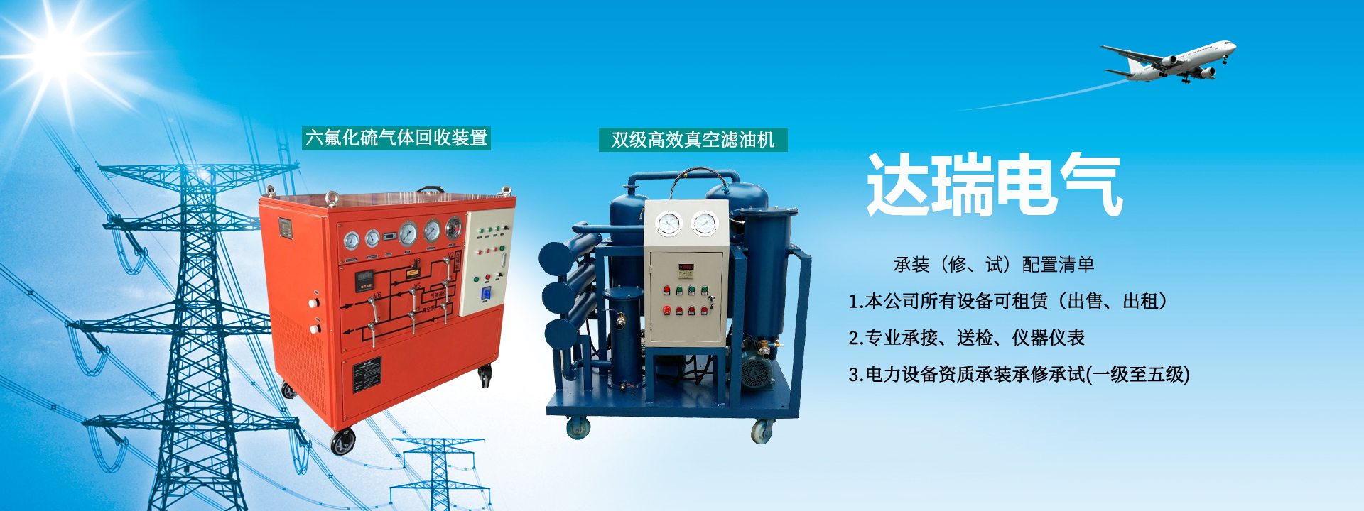
Application
Used for filtering ultra-high voltage transformer oil, suitable for treatment of 110KV—500KV power transmission and transformation equipment. On-site oil treatment and vacuum drying of damp electrical equipment. Vacuuming newly installed or overhauled transformers while performing vacuum oil filling.
Principle and Features
This machine adopts a combination of thin-film evaporation and drying for oil-water separation, equipped with matched (two-stage) vacuum pumping speed and heating power, and includes high-efficiency degassing elements, giving it excellent dehydration capability. At room temperature, the insulating oil treatment performance exceeds national standards. It uses composite micro-pore filtration technology with high dirt-holding capacity and high filtration precision. Compact and efficient, reliable operation, easy to move, especially suitable for on-site insulating oil treatment.
Working Flow Chart
Under vacuum, oil enters the electric heater through a coarse filter, then passes through a rotary separator into the vacuum degassing tank for oil-water separation. Water and gas are removed via the defoamer, cooler, Roots vacuum pump, and backing pump. The dehydrated and degassed oil is then transported by the oil pump to the fine filter to remove impurities, and purified oil is output.
IV. ZL-JS-50 Insulating Oil Two-Stage Vacuum Oil Purifier Technical Specifications
|
Oil Breakdown Voltage |
55 ~ 75 KV |
|
Water Content in Oil |
2 ~ 5 PPm |
|
Gas Content in Oil |
≤0.1% |
|
Impurity Particle Size |
≤1um, no free carbon |
|
Dielectric Loss Factor |
tgδ(90℃) ≤0.003 |
V. ZL-JS Insulating Oil Two-Stage Vacuum Oil Purifier Technical Parameters
|
Parameter Name |
Unit |
ZL-JS-50 |
ZL-JS-100 |
ZL-JS-150 |
ZL-JS-200 |
ZL-JS-250 |
ZL-JS-300 |
ZL-JS-500 |
|
|
Flow Rate |
L/min |
50 |
100 |
150 |
200 |
250 |
300 |
500 |
|
|
Working Vacuum Degree |
Mpa |
—0.08~ —0.099 |
|||||||
|
Working Pressure |
Mpa |
≤0.35 |
|||||||
|
Oil Breakdown Voltage |
Kv |
≥55 |
≥60 |
≥60 |
≥60 |
≥60 |
≥60 |
≥60 |
|
|
Constant Temperature Control Range |
℃ |
30~50 |
|||||||
|
Power Supply |
|
~50Hz 380V |
|||||||
|
Working Noise |
dB(A) |
≤70 |
≤75 |
≤80 |
≤80 |
≤80 |
≤82 |
≤85 |
|
|
Heating Power |
Kw |
26 |
63 |
72 |
81 |
90 |
99 |
108 |
|
|
Total Electrical Power |
Kw |
28 |
64 |
75 |
86 |
95 |
105 |
114 |
|
|
Inlet/Outlet Pipe Diameter |
mm |
32 |
40 |
50 |
50 |
55 |
65 |
80 |
|
|
Equipment Weight |
Kg |
500 |
800 |
1000 |
1200 |
1300 |
1450 |
1600 |
|
|
Overall Dimensions |
Length |
mm |
1500 |
1600 |
2100 |
2150 |
2200 |
2250 |
2300 |
|
Width |
mm |
1100 |
1200 |
1260 |
1300 |
1350 |
1500 |
1650 |
|
|
Height |
mm |
1400 |
1500 |
2100 |
2150 |
2200 |
2250 |
2300 |
|
VI. Installation and Commissioning
1. Connect the oil inlet and outlet pipes.
2. Connect the three-phase four-wire power supply according to the total power of the machine, and ensure the rotation direction of the backing pump, oil pump, and Roots vacuum pump matches the arrow direction.
3. Jog the backing pump, Roots pump, and oil pump to check for any jamming or eccentric vibration.
4. Check all oil, gas, and water pipelines for leaks.
VII. Operation Method
1. Start the backing pump. When the vacuum degree reaches between -0.08 and -0.095, start the Roots vacuum pump.
2. After the Roots vacuum pump starts, open the oil inlet valve.
3. When oil is sprayed from the observation window in the vacuum chamber, start the oil pump.
4. Start heating (temperature is usually preset).
5. During normal operation, observe the oil level gauge and maintain a balance between oil inlet and outlet.
6. When stopping, first stop the heating system, wait 3 minutes, then stop the Roots vacuum pump and backing pump, close the oil inlet valve, after residual oil is drained, stop the oil discharge pump, open the vent valve to bring the vacuum gauge to zero, and disconnect the air switch. Do not reverse the shutdown sequence.
VIII. Precautions
1. If conditions permit, connect the oil inlet of this machine to the lowest point of the oil tank to facilitate smooth removal of solid contaminants and water.
2. This machine uses a high-efficiency special vacuum separation tower. When water content is high, the vacuum degree should not be too high to avoid excessive vaporization and even oil spraying from the backing pump exhaust port. After several cycles, the vacuum degree can be gradually increased as the water content in the oil decreases.
IX. Accessories and Technical Documents Included:
1. One instruction manual.
2. One certificate of conformity.
3. One oil inlet and one oil outlet hose.
X. Common Faults and Troubleshooting